Telescope pointing and tracking errors can be divided into
three categories: errors that can be tagged to specific telescope
issues such as gear error, errors that are caused by the Earth's
movement and atmosphere such as refraction, and non-specific errors
such as consistent errors in a quadrant of the sky.
Two trends in amateur astronomy conspire to make pointing and tracking accuracy important: the small size of digital imaging (CCD) chips, and the prevalence of low precision mounts designed for casual or visual observing. Required pointing accuracy is on the order of several arcminutes, and ideal accuracy closer to 1 arcminute. Required tracking accuracy is on the order of an arcsecond over minutes of tracking time.
Most amateur telescopes are designed for visual use with the emphasis on low cost and rugged transportable hand pushed mounts. High precision pointing is not required from these scopes as the user will star hop to the destination. Experience with adding digital encoders or a computerized drive system to these telescopes reveal pointing errors in the ¼ degree or greater range. Consequently from a digital imager's viewpoint, or from the viewpoint of using digital setting circles to acquire objects at high power, the telescope points haphazardly. Sometimes the object is in the field of view and sometimes it's nowhere to be found.
If amateurs wish accurate goto pointing and tracking, the mounts need to be designed with precision in mind. A telescope must be precisely built: axes perpendicular, round altitude bearings, matched rocker side bearing points, flat rocket base, rigid tube assembly, and coincident optical and mechanical axes. The gearing should have little backlash and minimal periodic error that is slow changing.
Software corrections can add a great deal of accuracy if the errors are periodic, repeatable, and can be characterized or analyzed.
Consistent pointing to one arcminute is a worthy goal, giving
confident centering of objects on small CCD chips and in high power
eyepieces. If necessary, offsets accurate to arcseconds are easily
obtained by first centering on nearby objects. Blind across the sky
arcsecond accuracy enters a new realm. Here a whole barrel of
corrective factors must be actively calculated and applied. While
necessary for large professional scopes, this level of arcsecond
accuracy is not needed by the serious amateur.
Errors to
either eliminate by better design and construction, and further by
software compensation in order of importance and in order that they
should be tackled:
gear backlash
gear periodic error
correction (called PEC)
for stepper motors, physical variations in
the quarterstep spacings over the sequence of windings (called QSC
for QuarterStepCorrection)
drift
guiding
corrections
atmospheric refraction
precession
discrepancy
between the optical and mechanical axis in the vertical axis (called
Z3 or altitude offset)
axis misalignment (one side of the rocker
is higher than the other) (called Z1 or axis
misalignment)
discrepancy between the optical and mechanical axis
in the horizontal axis (called Z2 or azimuth offset)
altitude vs.
azimuth error correction (dobsonian rocker base levelness) (called
ALTAZEC)
altitude vs. altitude error correction (tube droop,
altitude bearing unevenness) (called ALTALTEC)
azimuth vs. azimuth
error correction (azimuth drive gear eccentricity) (called
AZAZEC)
nutation
annual aberration
residual errors, captured
as pointing model corrections (called PMC)
Gear backlash
is the deadband or momentary lack of motion when reversing direction.
Worms and spur gears cannot be run tight against the main gear as
they will bind or seize thanks to ever present no matter how small
gear eccentricity and worm mounting errors. So a tiny gap is left
between the worm and gear. When reversing direction, the worm will
rotate a small amount before it comes in contact with the preceding
gear tooth. During this time the main gear does not move. The main
gear is usually spring or gravity loaded by slight mis-balance of the
telescope, or, restrained by friction so that it does not bounce back
and forth. Multiple geared systems will have additive backlash.
Backlash of one gear will be taken out only after the backlash has
been taken out in the preceding gear set in the gear train. It's only
necessary to characterize the total backlash of the entire gear train
since at the eyepiece or focal plane, a multiple gear set appears the
same as a single worm and gear. Even in the situation where a
Periodic Error Correction curve is generated for each gear set in a
gear train, as long as a separate Periodic Error Correction curve can
be generated for each gear in both directions, individual backlash of
each gear set can be left undetermined. This is because when backlash
is entirely taken up in a direction, the gears will have a consistent
relative orientation.
To measure backlash, move the motor in one direction until all backlash is taken up. Note the displayed Current Altitude or Azimuth value. In daylight, sight through the telescope at a distance sharp edged landmark, or, aim a laser attached to the telescope at a marked point on a wall. Carefully and slowly move the motor in the opposite direction until the telescope begins to move. Subtract the updated Current Altitude or Azimuth value in degrees to get the backlash value. Multiply by 60 and enter the resulting value in arcminutes in the configuration file.
Gears have periodic errors thanks to slight eccentricities (main gear not precisely centered on shaft) and misalignments. Software can correct for these errors as long as they are periodic and thus predictable. There are two aspects of periodic error to consider: the total extent of the error, and how fast changing is the error. It is most important to have slow changing error. Gears and mounts are typically rated in terms of overall periodic error, especially as a marker of quality, but once the decision is made to guide either manually or by using an auto-guider, the most important rating is rate of change of periodic error. The slower changing the error is, the easier it is to guide out. The absolute total error at any one point is immaterial.
Periodic error can be characterized by recording guiding actions with the motor shaft angle over the desired period of time. Typically the most important gear to characterize periodic error correction for is the gear directly in front of the motor as it has the most impact on tracking errors. The gears further downstream, because they are geared down by the ratio of the immediate gear, change their error very slowly and can be ignored or leisurely guided out. If a quad turn worm, then the periodic error will cover four rotations of the motor. Typically the worm is a single turn worm and the periodic error will cover a single motor rotation. The motor shaft angle is marked arbitrarily to indicate a starting or synchronization point. It is popular to build auto-synch circuits that detect an infrared LED output as a hole in a wheel attached to the motor shaft is rotated to the correct angle.
Several cycles of guiding actions versus motor shaft angle are recorded. Each cycle should have drift subtracted (the difference between starting and ending values), any remaining offset subtracted (a constant value), and median smoothed. Then the cycles are averaged together. When tracking the periodic error curve is played back as motion commands to the motors above and below their otherwise steady movement.
Depending on the quality of the gear and worm, and depending on backlash if the gear in question is further downstream, it may be desirable to build PEC for each direction. When a scope reverses direction, the opposite side of each gear tooth is used along with the opposite side of the worm's threads. There may be enough variability to matter.
For more on PEC and how my software handles periodic error
correction, see my page operate_pec.html.
Telescope coordinates are translated to celestial coordinates
using an alignment model. This model will be very simple in the case
of an equatorially aligned telescope where altitude matches
declination and azimuth matches hour angle (local sidereal time minus
right ascension). For altazimuth telescopes, the modeling is more
complex. Lesser used models include algorithms such as matching
angular separation, and, more simply, tracking via automated
following. More commonly used is a model based on spherical
trigonometry formula. These formula call for entering the latitude
and longitude of the observing location, precisely leveling the base,
then finding stars using an accurate clock.
I use the
model popularized by Taki. He uses a matrix of directional cosines to
convert between telescope and celestial coordinates. The telescope
pointing values are calculated from the telescope's altitude and
azimuth, and time at the moment the object is precisely centered in
the field of view. For instructions on how to initialize the
telescope to the celestial sphere, see the operate software - equat
startup, or, operate software - altaz startup webpages.
Drift
is caused by pointing errors. Positions to track to, or, velocities
to track by, are calculated based on assumptions of how the telescope
is aligned to the sky. Inaccuracies in this alignment will cause the
object to appear to slowly drift away from the center of the field.
Drift can be nulled by setting my software in the guide + drift mode,
and following an object for a couple of minutes. Centering the
object, then pressing a button on the hand paddle, causes drift to be
calculated and automatically adopted. Use drift nulling to precisely
track an object for long exposure imaging on CCDs or film. Drift will
slowly change as the telescope tracks for hours into a new portion of
the sky. Drift should be set to zero before slewing to new
object.
Refraction is caused by the atmosphere, making objects
near the horizon appear higher in the sky than they really are. Don't
turn this on unless you have an altazimuth mount that is reasonably
level. Also, don't turn this on until backlash compensation is
working.
One advantage of the Taki routines is that the
azimuth need not be precisely set at startup time. That is, one does
not have to set zero azimuth precisely north or south. Instead, the
routine relies upon the difference between azimuths. So the starting
azimuth can be any value since we need only measure the change in
azimuth as the telescope moves. Unfortunately, the conversion
routines require that the starting altitude be precisely known.
However, by using the idea of matching the angular separation given
by the celestial coordinates to the angular separation given by the
telescope's coordinates, the correct altitude can be deduced. This
means that the starting angle of neither axis need be precisely known
at startup time. The altitude offset can be done as soon as the two
stars are initialized. It is best to use two stars at about the same
altitude with widely differing azimuths. The altitude offset is
called Z3 by Taki. Since the initialization points can vary if Z1 and
Z2 are present, altitude offset may not be precisely determined by
utilizing only two stars. A series of points well scattered across
the sky will allow the Z1 and Z2 errors to be averaged out. The most
accurate altitude offset then is obtained by averaging all the
altitude offsets found by comparing each possible pairing of
coordinates. About a dozen of these analysis points, well placed
across the sky, can result in an altitude offset accurate to half an
arcminute. A very accurate altitude offset, or Z3 error, is critical
in separating the Z1 and Z2 errors from each other.
Z2 is the
azimuth offset error, or the difference between optical and
mechanical axis in the horizontal plane. Z1 is the degree of
misalignment between the telescope's two axis. Think of one side of
the rocker arms being higher than the other side: the axes are no
longer exactly perpendicular. Z1 causes a growing azimuth error as
the scope is moved towards the zenith, while Z2 is a constant azimuth
error. However, as the scope is aimed further skyward, while Z2
itself stays constant, the affect on the scope's pointing is to make
the azimuth error appear to grow. The lines of azimuth shrink as the
scope approaches the zenith, so the apparent azimuth error increases.
This mimics the Z1 or axis misalignment closely. Not only that, but
investigating Taki's coordinate translation matrices shows that Z1
and Z2 are tangled and cannot be separated or solved for independent
of each other. Instead, an iterative approach must be adopted, not
only in Taki's routines themselves when converting from equatorial to
altazimuth coordinates, but also in any routine that attempts to
analyze sky positions to deduce the Z1 and Z2 errors.
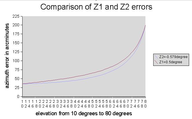
Consider the following graph. Here I derived Z1 and Z2 errors that result if the scope is centered on a star at 10 degrees elevation, and on a star at 80 degrees elevation. Note that opposite Z2 mimics Z1. The difference between the Z1 and Z2 curves is very subtle, amounting to a handful of arcminutes at a between elevation. The challenge of calculating the proper Z1 Z2 is further compounded when considering that real world Z1 Z2 values are likely 1/4 to 1/2 of those used to generate the graph, that Z1 and Z2 are likely present in some unknown mix, and, that the accuracy of azimuth measurements at high elevations is reduced by the cosine of the elevation. At 80 degrees elevation, measurements will be almost six times less accurate.
After accurately determining Z3, by analyzing a series of positions, Z1 Z2 values can be obtained that minimize rms pointing error. While it may appear troubling that Z1 Z2 cannot be more assuredly and accurately determined, because the values are so easy to substitute for each other, the predictive ability is best served by using Z1 Z2 values that do result in the lowest rms pointing error.
Changing the collimation, or moving the mirrors, or doing anything to change the horizontal angle between the optical and mechanical axis will necessitate re-measuring Z1 and consequently Z2. The Z3 - Z1-Z2 cycle can be repeated based upon another round of position analysis, where the errors in altitude and azimuth for each star are saved.
The Z1Z1Z3 errors, the ALTAZEC errors, the ALTALTEC errors, and the PMC errors all rely on the same analysis file. When an error has been corrected for, the next error in the list can then be worked. The errors must be corrected for in order, though you may skip any of the error corrections.
Here's a plot of Tom Krajci's 16 inch - RMS error is about 3 arcminutes:
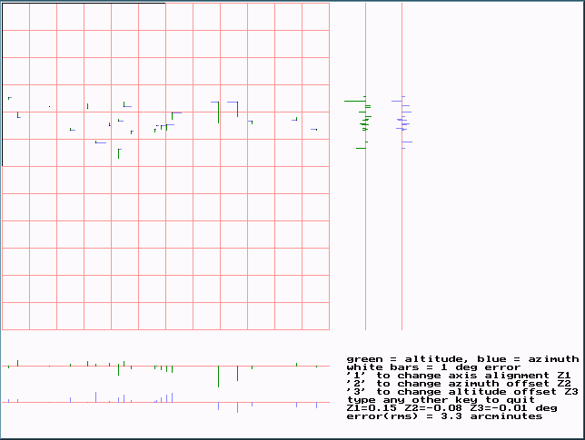
After Tom analyzed his mount and adopted Z1 Z2 Z3 values, and corrected for a lumpy rocker bottom, his rms improved to 1/2 arcminutes pointing.
After Z1, Z2, and Z3 are set, the ALTAZEC and ATLALTEC and AZAZEC and PMC correction curves can be added.
Finally, residual errors are handled by General Pointing Model Corrections, called PMC, can be analyzed and adopted. These errors, unlike the errors mentioned so far, are not specific to a feature or characteristic of the mount, but instead, are generalized pointing instructions to improve goto and tracking accuracy in specific sections of the sky.