Stepper System for Computer Control of Telescopes
Designed in the late 1980's, the stepper system was sold for many years until 2012.
Safety Guide and Warning
You must exercise proper safety precautions, including the wearing of safety glasses, thermal and electrically insulated gloves, and thick rubber lug shoes.
Shock hazard! Bodily injury hazard! Any device using electricity is a shock and bodily injury hazard. You must hook up the device properly and follow all safety precautions, particularly when using electricity outdoors. If improperly hooked up or improperly operated, electronic components can shock, overheat, melt, and explode.
Peripheral equipment hazard! Any device electrically attached to a computer can damage the computer if hooked up improperly, or used improperly.
In particular:
1. never operate when the equipment or cabling is wet or moist, even if there is only a possibility that some of the equipment is wet or moist
2. all grounding points must be connected to the battery (-) terminal before turning on any equipment; the grounds must never be disconnected while the unit is powered on (disconnecting any ground will force the current to search out a return path to ground, possibly by traveling through the handpad and parallel port data lines into the parallel port and motherboard, possibly damaging the circuit board, handpad, parallel port, and motherboard, and possibly causing shock and bodily injury)
3. power leads must be connected in proper order with the black ground wire connected before the red positive voltage lead
4. power leads must not be reversed: instant component failure is a certainty; components will overheat and can explode with violent force
5. do not exceed 12 volts DC power input
6. the power supply (+ or positive voltage) lead can only be connected or switched on when the software scope.exe is executing, and if running under Windows, can only be connected or switched on if scope.exe is the foreground program
Stepper Quick Start Guide
1. Re-read the Safety Guide and Warning
2. attach the circuit board to the computer's parallel port using a straight through 25 pin serial cable
3. attach the hand paddle to the circuit board
4. using a small 12 volt battery, or two 6 volt dry cell batteries connected in series, attach the battery's (-) post to the circuit board ground, which will be the black lead
5. turn on the computer
6. enter the appropriate parallel port in the config.dat file: look near the end of the file for a line that starts PportAddr, and enter the desired lpt #, usually a 1
7. run scope.exe, selecting either altazimuth or equatorial alignment
8. attach the battery's positive (+) post to the circuit board's red lead
9. check the hand paddle operation by pressing the hand paddle buttons in turn, verifying that scope.exe is reading the buttons properly
10. using the optional LED tester unit, plug it into the altitude or the azimuth motor port (do not plug it into the field de-rotator port), then turn on tracking in scope.exe, and verify that a. the lights turn on and off in sequence from one side to the other, and b. no more than 2 lights are on at any one time
11. verify motor movement by attaching a motor to the azimuth/right ascension port of the circuit board (the middle db-9 connector), then turn on tracking in scope.exe
12. attach the other unipolar stepper motor to the altitude/declination port of the circuit board and verify movement by using the up button of the hand paddle
13. if using a bipolar field rotator motor, attach it to the field rotator port (the bottom db-9 connector, next to the raised IC), then set the altitude to 80 degrees in scope.exe
Stepper Software Notes
config.dat settings:
set InvertOutput to 0 in config.dat.
Original designed called for 7404 inverters to drive the transistors, hence InvertOutput 1 in the original config.dat (parallel port output goes high, hex inverters go low, and drive transistors turn off, hence the need to invert the output).
In the original design, if opto-isolators were used, then InvertOutput 0 (parallel port output goes high, hex inverters go low, opto-isolators turn on pulling output low, hex inverters go high, and drive transistors turn on, hence no need to invert output).
This pcb design uses 7408 and gates (parallel port output goes high, 7408 and gates go high, opto-isolators turn off allowing output to return to high, 7408 and gates go high, and drive transistors turn on, hence no need to invert the output).
Stepper Hardware Notes
heatsinks:
no heatsinks are required on the power transistors as the software ensures that only the needed current is sent to the motors, for instance, 1 amp motors typically draw 0.1 amps while tracking and slewing; a heatsink on the 7805 voltage regulator might be required if you jumper it so as to power the computer side of the board and then use the board in poor ventilation or warm temperature (current draw with motors off at 12 VDC is 0.22 amps), or with higher drive voltages up to 24 VDC;
*** note by Pat Sweeney: I found that if the motors draw less than 1 amp each the transistors do not get hot while slewing or tracking. Currents of 4 or 5 amps while ramping up or down also are OK. If currents of around 2 amps per motor are expected. insure cooling via a small fan blowing on the TIP120s If currents much above 2 amps are expected I would suggest heat sinks But they must be electrically isolated. the collectors are tied to the tab on the TIP120s ***
motor sizes and current limit:
Use unipolar steppers in the range of 6 to 12 volts with amperage of 0.5 to 1 amps and winding or coil resistances of very roughly 5 ohms. Smaller and lighter motors will work also, even for rather large scopes. You can find these in old floppy drives, for instance. If the motor winding or coil resistance is 1 ohm or less, then the output power transistors will likely burn out in seconds. If you need to use more powerful motors of 1 to 3 volts with amperage up to 4 amps, then add either series power resistors, or better yet, install the current limiting add-on circuit designed by Jean-Charles Vachon. Here are the details: Current Limiting Addition by Jean-Charles Vachon
power/ground connections:
the 6 holes for power and ground go as follows (board face up with the 6 holes to the lower left, starting from the hole closest to the DB25 connector and finishing with the hole closest to the board's edge):
computer side of the PCB::
1. gnd (optionally jumper to the motor side gnd #5)
2. +5 vdc (optionally jumper to 7805 +5vdc output pin ([turning board upside down, the outside most pin of the 7805])
3. gnd
motor side of the PCB:
4. +12 vdc
5. gnd
6. +12 vdc
for complete isolation, use separate computer and motor grounds, and supply an external +5.0 VDC source for the computer side or use the +5VDC output from pin 1 of the joystick port DB15; the vast majority of us will not require this total isolation, instead, tie computer and motor grounds together, and supply the computer +5 VDC from the 7805 power regulator (U6 - it will get hot supplying both sides of the board so consider a heat sink if not well ventilated or used in hot clime): do this best by jumping 1. gnd and 5. gnd together, then jump the bottom lead of the 7805 to 2. +5 vdc, and finally bring out two wires from 5. gnd and 6. +12-24 vdc for the ground and positive power connection respectively;
Be very careful when testing so as to not risk your computer's parallel port. Use a 6 volt drycell battery for motor voltage during initial testing.
*** note by Pat Sweeney: I left the computer 5volt supply separate from the 12 volt supply to isolate the parallel port from the drive circuit. If a catastrophic failure on the drive circuitry occurs there is the possibility of wrecking the parallel port on the computer. If + 5 volts is not available from the computer for this then I suggest using a small isolated DC to DC converter off the 12 volt side. I found that a 12 to 9 volt 250 mA DC to DC converter from JAMECO Part # 153736 for $1.95, and, a 5 volt regulator will provide the isolation for my laptop. ***
9/25 pin connectors:
circuit board 9 pin and 25 pin connectors are straight (not angled) connectors; use thin flat cable to connect these to a set of connectors that you have mounted in the electronics box's face plate;
*** note by Pat Sweeney: you can mount all but the 25 pin parallel port connector from underneath on the solder side ***
Stepper Field Rotator/Focuser
The optional field derotator/focuser chip can be added later. The circuit board was designed with the SAA1042 in mind. However, the now discontinued SAA1042 has been replaced by the MC3479 (or ECG1859). Here's a graphic of the MC3479 installed with the modifications on the pcb:

*** following note on how to hook up the MC3479 and ECG1859 by Bob Norgard ***
Three pairs of wires need to be reversed to make it function properly with the circuit board, plus a resistor needs to be added. Get a little daughter board designed to handle a single IC chip of 16 pins to float above the field derotator socket. Pins 1&2, 16&16, and 8&9 need to be reversed. Cut 15 pieces of insulated 22 ga solid hookup wire 3/4 inch long. Take a 2k ohm 1/4w resistor and trim its leads to the same overall length. Solder one end of the resistor to pin #11 of the 16 pin socket. Additionally, the existing 56k bias resistor may not be optimum for different motors. The MC3479 handles up to 350 ma motors while the ECG1859 handles up to 500 ma motors. The stepper can handle larger amperage motors with Chuck Shaw's modifications mentioned below (be sure to still swap the 3 pairs of leads for the new chips).
Main_Board ECG-1857 Board
SAA1042 site
1* 2*
2* 1*
3 3
4 4
5 5
6 6
7 7
8* 9*
9* 8*
10 10
11 2K* 11
12 12
13 13
14 14
15* 16*
16* 15*
* Note lead reversals and added 2K resistor!!!
I mounted the little board using 4 stand-offs inside the aluminum box that houses the rest of the drive circuitry. For testing purposes, I used a Mitsumi Electric M68SP-4 12V/33ohm stepper salvaged from an old floppy drive. It has 1.8 degree steps. The chip ran barely warm to the touch.
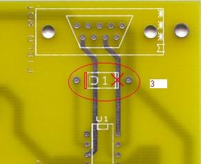
*** note by Pat Sweeney on the field derotator/focuser portion of the pcb ***
The schematic and silk screen does show the 3.9 volt zener in backwards. (sorry ) The rest of the circuit is OK. The chip is configured to drive a 2 phase bipolar stepper motor. (4 wire motor) I tested the circuit on a stepper that draws 200MA per winding and it seems to work properly. Only the pins 6,7,8,and 9 are used. Pins 1,2,3,4, and 5 can supply + 12 volts for external transistors to power a stepper that will draw more than 500MA. Ground for external transistors will have to be supplied from another location on the board.
I wrote a program fldrot.exe (download here) that will run from DOS or WINDOWS 3.1 & 95 . It will step a bipolar motor 1 step per second for 200 steps forward and then 200 steps in reverse and continue in this mode until "Q" is pressed. It should help in debugging the circuit. Note don't have the ALT or AZ motors attached while using FLDROT.EXE.
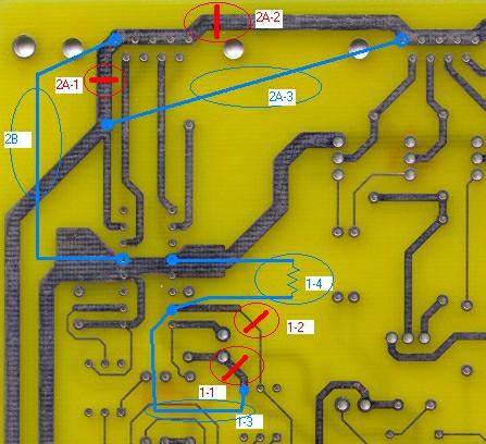
*** note by Chuck Shaw on how to modify the field derotator/focuser portion of the pcb for a unipolar stepper ***
select here for Chuck's note
select here for Chuck's circuit mod
select here for Chuck's pcb mod graphic #1
select here for Chuck's pcb mod graphic #2
Soldering Tips
� orient the board so that the parallel port 25 pin connector is to the left
� the tip 120 transistors will face to the bottom, and the mje 3055 and 7805 voltage regulator will face to the left
� the diodes must be soldered so that their banded marking matches the diode marking on the pcb
� some capacitors have a long leg - these solder into the '+' marking
� all the opto-isolators solder in with the alignment marker to the top of the pcb, (alignment marker is to the upper left of the indented side)
� make sure you mount the 7408 AND gates so that the alignment marker is either to the top or to the right
� do not overheat components while soldering: solder one lead, then move onto the next part, returning later to solder the next lead
� double check all solder joints before applying power
� before mounting the 7408 AND gates, apply power and verify the ground and +5 VDC lines through the pcb, and particularly at each 7408 AND gate
� use a straight through 25 pin to 25 pin connector with male ends on each side to connect the parallel port to the pcb
� be careful to not cause a short if using metal screws to attach the DB9 connectors to the circuit board
� after mounting the 7408 chips and before attaching the stepper motors, use the parallel port test option of scope.exe to exercise the output lines and verify with a voltmeter that the 8 output lines to the 2 steppers are functioning properly
Handpad
here's the handpad circuit diagram
here's how I solder the handpaddle circuitry
1 handpaddle plastic box Jameco 18922 (3.1"x2"x.9"ABS) $3.15 or Mouser 546-1591BS-BK (4.4"x2.4"x1.2"ABS) $3.34
6 push button momentary on switches Jameco 26622 $.49
1 2-way switch Jameco toggle 21936 $1.09
6 small diodes Jameco 35991 $.40/10
1 RJ11 connector Jameco 124039 $.95
Here's how Ned Smith built his handpad:
I used the following from TechAmerica (RadioShack): 910-1075 $15.48 It is a 1 x 2.4 x 3.8 inch enclosure with a membrane
switch pad. It has a 3 x 4 switch array. I cut off one row to make a 3 x 3. This gives me Up, Down, Right, and Left. I used the upper R and L corners for the for the self-centering toggle switch. I only had to add SPDT to handle the two stepping rates. The membrane switches add about 50 ohms to the circuit which reduced the voltage at the connector. I used RJ12 connectors for the hand paddle to PCB enclosure and stepper motor to enclosure.
handpad cable:
cable: 10 foot length of flat 6 wire Jameco 103448 ($.07/foot)
connectors: (2) RJ11 6p Jameco 79273 $.15
Using RJ11 connector with straight through cable (comparing cable ends side by side with clips up, wiring is the same color sequence from left to right), hookup is:
pin number looking face-on to connector with clip on top:
******
*******************
* rd wh ye *
* bk gr bl *
*******************
parallel port pin 13 is the yellow wire
parallel port pin 12 is the red wire
parallel port pin 11 is the white wire
parallel port pin 10 is the black wire
+5 VDC is the blue and green wires
Using RJ11 connector with crossover cable, hookup is:
pin number looking face-on to connector with clip on top:
******
*******************
* rd wh ye *
* bk gr bl *
*******************
parallel port pin 13 is the black wire
parallel port pin 12 is the green wire
parallel port pin 11 is the blue wire
parallel port pin 10 is the yellow wire
+5 VDC is the white and red wires
PCB and Parts List
here's the printed circuit board circuit diagram
Use the part numbers here and on the printed circuit board - any part numbers on other circuit diagrams do not necessarily correspond to the pcb
click here for parts layout
Here are the circuit board graphics: pcb_graphics.zip
All capacitors are in microfarads and all resistors are 1/4 watt: there is a fair degree of latitude in selecting parts.
1 C1 4.7/35V tantalum cap Jameco 33806 $.35
1 C2 47/35V electrolytic cap Jameco 31114 $.15
6 C3-C8 0.1 monolithic cap Jameco 25523 $.15
1 D1 3.9V/1W zener Jameco 178765 $.12, Allied 568-0135 $.08
8 D2-5, D7-10 1N4004 diode Jameco 35991 $.40/10
4 D6, D11-13 30V/1W zener Jameco 178925 $.08, Allied 568-0045 $.06
10 ISO1-10 4N35 optoisolator Jameco 41056 $.35 (optional socket Jameco 112192 $.08)
1 P1 DB25F connector Jameco 15165 $.65
3 P2-4 DB9F connector Jameco 15780 $.49
2 Q1-2 2N2222 transistor Jameco 28628 $1.10/10
8 Q3-6, Q9-12 TIP120 transistor Jameco 32993 $.65
4 Q7-8, Q13-14 MJE3055 transistor Jameco 25857 $.65
14 R1-4, R6, R10, R12, R14, R17-18, R26-27, R29, R31 220 ohm resistor Jameco 30470 $.89/100
1 R5 56k resistor Allied 526-1666 $2.94/200
11 R7, R9, R13, R15-16, R19, R24-25, R28, R30, R38 4.7k resistor Jameco 31026 $.89/100
4 R8, R11, R32, R372.2k resistor Jameco 30314 $.89/100
8 R20-23, R33-36 470 ohm resistor Jameco 31165 $.89/100
1 RJ11 RJ11 connector Jameco 115836 $.65
1 U1 MC3479 IC (replaces SAA1042) Jameco 25216 $5 (needed only if you will be doing field derotation or motorized focus control)
1 socket 16 pin Jameco 37372 $.07 (needed only if you will be doing field derotation and using the SAA1042 chip; for the MC3479 chip use wire wrap socket Jameco 37411 $2.25 with 2.2k resistor Jameco 30314 $.89/100 as 3 pairs of wires need to be reversed and one lead replaced with the resistor)
4 U2-5 74LS08 IC Jameco 46375 $.25
4 14 socket pin Jameco 37161 $.06
1 U6 7805 regulator Jameco 51262 $.29
optional TO-220 heatsink for the 7805 Jameco 107297 $.39 (heatsink compound Jameco 167249 $7.95)
(solder Jameco 141778 $13.95)
Computer Operated Telescopes
How-To
So, you've decided to check out motorizing your telescope. Perhaps you saw another tracking telescope and wish the same ability for your scope, perhaps you want the goto ability in your light polluted skies with few signposts, or perhaps you want to try your hand at CCD imaging. As you surf through the wepages, you may feel overwhelmed by the material and the many options. What to do?
- Get the circuit board, hand paddle, and cabling (you can purchase stepper and servo systems from me)
- Get two surplus motors, either steppers (5 leads or more), or, servos with optical encoders, and two small gear reducers of about 50:1
- Get a cheap pc or laptop (suitable used laptops average $100)
- Hook up the components and get the motors to track and slew while holding them in your hand
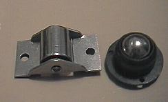
- Switch teflon pads to small bearings:
- Replace formica bearing surfaces with sheet metal
- Make one of the bearing points in each axis a small drive shaft that is attached to the small gear reducer
- Get optional encoders and encoder interface box
- Configure for your particular combination of parts
- Total cost ~$100 - $500 for the stepper version and $300 - $700 for the servo version
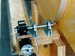
Inexpensive bearing ideas
 |
altitude axis with 60:1 gear reducer feeding a 30:1 roller drive
 |
News and links
My first fully computer operated telescope, the 20 inch [0.5m] (1992)
early CCD imaging with the 20 inch (1995)
ultralight computerized 20 inch (2002)
Chuck Shaw's computer operated telescope ATM pages
Berthold Hamburger's computer operated telescope pages http://www.astro.artinso.com/
Ben Davies has extensive documentation culled from the scope-drive@yahoogroups.com discussion group of 2500 enthusiasts http://ben.davies.net/scopemanual.htm
Chris Rowland has developed GPS software to connect scope.exe to GPS units via a serial port. See http://groups.yahoo.com/group/scope-drive/files/Other_Software/gpsscope_v2.zip
Chuck Shaw and Ben Davies develop modem to modem communications, allowing laptops with one comm port to add an additional serial port for encoder and planetarium control.
French translation of these webpages http://ftissera.free.fr/Webmel/altaz.html
German version of scope.exe http://www.gotodobson.de/software.htm
German translation of the webpages by Yvonne and Alexander Urban http://www.geocities.com/alexanderurban/melspage/altaz.html
Italian translation of the webpages by Marco Bagaglia
Loboyko Steve [sloboyko@yahoo.com] touchscreen modification
Martin Niemi's quickcam autoguider now outputs guiding commands via a serial port using LX200 compatible commands, which scope.exe understands.
Larry Strange's innovative mouse encoders LarryStrangeInvention.html
article appearing in May, 2000, Circuit Cellar magazine
article appearing in April, 2000, Sky and Telescope magazine
join the scope-drive mailinglist
the scope-drive archives
Download Free Stepper Software
(servo software may be ordered here)
stepper software licensed under GPL, see http://www.fsf.org/copyleft/gpl.html
if you have trouble, e-mail me and I will e-mail you back the files
download the executable program (2009-March-26 310kb)
download the source code (2007-Sept-1 240kb)
download the associated data files, epoch 2005 (2005-Sept-11 675kb) NGC and IC1-IC5 data contributed by Don Ware are taken from NGC 2000.0, edited by Roger W. Sinnott.Copyright (c) 1988 by Sky Publishing Corp. Reproduced with the permission of the publisher.
http://www.geocities.com/kindellism/ here you will find solar system and comet calculator programs by Rex Kindell


![My first fully computer operated telescope, the 20 inch [0.5m] (1992](20inch-1994.jpg)